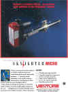
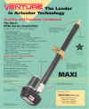
CHANNEL MASTER LINEAR ACTUATOR MODEL 6375
12-36VDC
BUILT IN ADJUSTABLE LIMIT SWITCHES
POWDER COATED
18" THROW
UP TO 1,000 LB THRUST (400LB RECOMMENDED LOAD)
SUPPLIED WITH MOUNTING BRACKETS
DESIGNED FOR OUTDOOR USE
These brackets originally made for moving very large satellite dishes are
possibly more suitable for closing gates, mechanical machinery, robot wars etc.
Our first sale was to a company building solar panels that track the sun!
Two sizes available, 12" and 18" throw.
 Click
to enlarge Click
to enlarge
 Click
to enlarge Click
to enlarge
The following text is taken from the 18" version
RETRACTED (LOWER) LIMIT RECALIBRATING
ACTUATOR ELECTRICAL END STOPS
Power is supplied by a reversable 36 volt DC motor driving the
shaft through a gear reduction. The screw shaft causes the
piston rod to travel in and out over its 18" range. An adjustable
limit switch at each end of the travel shuts the motor off when
actuated by the limit rod. A sensor is provided to remotely
detect antenna position.
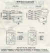
Terminials 1 and 2 on the terminal strip are connected to the
motor through limit switches LS1 and LS2. Each limit switch is
jumpered with a diode which allows power to flow in the
reverse direction of that which caused the switch to be open. A
positive voltage on terminal (1) will cause the piston rod to
extend. A positive voltage on terminal (2) will cause it to
retract.
The actuator electrical limit switches have been factory calibrated
to engage 1/4 inch before the actuator reaches its mecchanical
end stops (end of acme screw travel).
NOTE: This procedure Must be performed if the inside limit
shaft has been rotated prior to installation on the antenna
system.
1. Place actuator on a flat surface. Hook up the actuator to the
receiver as outlined in the antenna assembly manual.
2. DO NOT restrict inside shaft rotation or travel.
3. Push the button that causes the inside shaft to contract
towards the motor housing. Continue to hold the button
down until the MOTOR stops.
NOTE: The shaft may reach its end stop (mechanical) and
begin to rotate before the motor stops. This is a sign that the
electrical stop is out of adjustment. Continue holding the
button until the MOTOR stops.
4. Now that the motor and shaft have stopped, manually
unscrew the inside shaft 3-4 turns. If the shaft does not
rotate before limit is reached, screw shaft in until motor
rotates, then screw it out 3-4 turns. The arrow label on inner
tube should be even with the wiper on the outer tube. See
sketch.
5. The above procedure will ensure that the electrical stop is
reached before the mechanical stop.
WARNING: FAILURE TO RESET THE END STOP SAFETY SWITCH WILL CAUSE
PERMANENT DAMAGE TO THE GEAR ASSEMBLY & VOID WARRANTY. JACK
MUST NOT BE ALLOWED TO RUN INTO MECHANICAL STOP AT EITHER END OF
ACME SCREW TRAVEL.
CALIBRATION OF ACTUATOR ELECTRICAL EXTENDED
(OUTER) LIMIT END STOP
The actuator electrical limit switches have been factory cali-
brated to engage 1/4 inch before the actuator reaches its
mechanical end stops.
To change these adjustments, follow the procedure below:
1. Set lower limit of travel of actuator when retracted by run-
ning actuator all the way closed (fully retracted).Loosen
four bolts in mounting bracket and slide actuator shaft
through mounting clamp until antenna is aimed a few
degrees below the first satellite closest to the horizon you
wish to receive at the end of azimuth travel.
2. Extend setting if less than 18" travel is desired.
Run actuator shaft out until antenna is aimed a few degrees
beyond the satellite to be received at the opposite end of
azimuth travel. Loosen stroke adjusting rod lock screw and
slide rod towards extension limit switch until contact is
made with the switch button. Tighten screw and check
antenna travel from one end to other of satellite belt.
Replace the motor cover on the actuator.
WARNING: DO NOT EXCEED BEYOND FACTORY SET 18" TRAVEL OR JACK MAY
HIT MECHANICAL END STOP AND CAUSE PERMANENT DAMAGE
AND VOID WARRANTY.
NOTE: Tighten 5/16" clamp bolts to 12ft.lbs.and 1/2" bolts to
25 to 30 ft.lbs.torque.
 Click
to enlarge Click
to enlarge
|